SATA Power Switch
My PC set-up consists of at least 2 OSs, one for everyday life, one for gaming. Occasionally there is another I’m playing with, or trying to learn something, but I always go back down to 2. Many people often dual-boot different OSs very successfully, right up until the point where one OS does something the other OS does not like. Having hit this scenario a few times, I decided to build a SATA power switch.
- Have you ever broken you dual-boot?
I have more than I'd like to admit. - Sick of Linux and Windows not playing nice together?
Absolutely.

Dual-boot Options
Dual-boot Options
- Daily driver Linux (Fedora is my preference)
- Dedicated Windows 10 for gaming (Windows still has the best gaming support)
- Alternative Linux I’m testing (Currently Arch, an ongoing challenge)
As an example, every time you install Windows, it is oblivious that other OSs can exist, overwriting any boot configurations you may have with an iron fist, leaving you with Windows being the only OS that can successfully boot. On EFI systems this is a bit better, since EFI can boot other partitions easily, but you will have too keep hitting that F# key during boot. I know Windows does this, I expect it, I plan for it. Prepared to reinstall and configure grub2 after a Windows install.
There are many other scenarios that exist, one that I most recently faced was, failure to boot Windows. I had stupidly made my /boot partition too small, so I couldn’t upgrade my kernel (not sure if I simply wasn’t thinking, or forgot to add a 0 on the end of the partition size). The resolution is fairly straightforward, to clean-up the /boot partition and squeeze in the updates, but this did not feel like a long-term solution. Long-term is definitely my way of thinking. What I had looked like below (I don’t remember exact sizes).
[philip@desktop ~]$ df -h
Filesystem    Size    Used    Avail    Use%    Mounted on
/dev/sda1     200M     19M     921M    9.5%    /boot/efi
/dev/sda2     200M    190M      10M     95%    /boot
/dev/sda3      16G     ---      ---     ---    SWAP
/dev/sda4     100G     44G      56G     44%    /
/dev/sda4     100G     44G      56G     44%    /home
/dev/sda4     100G     44G      56G     44%    /run/mnt/fedora-btrfs-root
My long-term fix was to make the /boot partition larger, by moving the swap partition and utilising the freed up space. I have set-up fstab and grub2 to use UUIDs, so changing partitions should not be a huge concern. The first and second step went smoothly, to create a new swap at the end, flip that to active, then clear the old swap to create free space. The second step to expand /boot, check/update fstab and grub2 just in-case, then rebooted Linux successfully.
[philip@desktop ~]$ df -h
Filesystem    Size    Used    Avail    Use%    Mounted on
/dev/sda1     200M     19M     921M    9.5%    /boot/efi
/dev/sda2     3.9G    245M     4.4G      6%    /boot
/dev/sda3      10G     ---      ---     ---    NA, unused
/dev/sda4     100G     44G      56G     44%    /
/dev/sda4     100G     44G      56G     44%    /home
/dev/sda4     100G     44G      56G     44%    /run/mnt/fedora-btrfs-root
/dev/sda5      16G     ---      ---     ---    SWAP
So what’s the problem? Windows. Windows refused to boot at this point, throwing the system into the Windows recovery interface, which is full of useless hanging actions that end in telling you to reboot and hope for the best. This isn’t the first time Windows has done this, let’s try correct it. After a few hours of attempts I gave up.
The Windows recovery environment, which is the running process on the system, could see the C:\ partition, as I could browse the contents. So a running Windows process, with access to the Windows installation partition, can’t boot itself. I’m no system boot engineer, but I felt like this was all the pieces of the puzzle, but Windows was just being awkward once one thing is a bit out of line. If this was Linux, I would simply chroot to the C:\ partition, correct/update any boot config, reload. But this is Windows and I’m not aware of such capability.
Solution Options
How do I stop this in the future?
- Don’t change partitioning, or grub2, or EFI…
- Don’t dual-boot…
- OS on separate disks…
- OS on separate disks and switch off unused…
Don’t change
- Simply not realistic, things always change
- Wouldn’t be able to try new technologies, learn, play
- Some things are simply out of my control
Don’t dual-boot
- Running just Linux
- Game support on Linux is next to nothing unfortunately
- Gaming is my relaxation, whereas many watch Netflix, I play games
- Many old friends game too, so a good way to not lose touch
- Running just Windows
- Too restrictive, frustrating, cumbersome
- Cumbersome for programming, docker, even simply SSH, etc
- Windows will get bloated meaning more regular reinstalls
- No control of experience, it’s “Microsoft’s way or the highway”
- Separate PCs
- Too costly, too much space used
- Desk is set-up for one PC tower and one work laptop with my monitor (which has a built in KVM switch for dual inputs and keyboard/mouse switching based on input choice)
- Does offer the most separation, a bit too much, adding additional hardware to manage
Physically separate the disks
- Both available, still dual-boot
- Re-partitioning disk A doesn’t affect partition order on disk B
- Need to manage
grub2to boot Windows grub2can still cause problems in booting Windows- Requires additional disks & SATA connections
- Requires waiting for
grub2selection menu to select (no grabbing a tea as I reboot)
OS on separate disks and switch off unused
- One available at a time, single-boot, power is cut off to other disk
- Not an approach I’ve seen, I had never heard of it till I looked deeper
- OSs only ever see their disk, never can read or write to other
- Re-partitioning disk A doesn’t affect partition order on disk B
- No need to manage
grub2to boot Windows - No requirement for waiting for
grub2selection menu to select (I can grab a tea as I reboot) - Requires additional disks & SATA connections
- Requires manual selection before booting, to cut power to unwanted disk
- Is the option I chose to pursue
Solution Design
I decided to go with the ‘OS on separate disks and switch off unused’ option, as this offered enough separation that any issue to one disk does not affect the other. Also by switching the power to the disks, the system will not try to boot one over the other, so no need to manage grub2 to boot Windows. As far as each of the OSs are concerned, they own the disks, they are the only OS. Anything can happen without breaking the other, from partitioning, to boot loaders, even EFI changes.
The closest reference to this approach was here, titled as a “SATA Hard Drive Switch”, which it is not. It does not switch SATA data cable in any form, that is a much different route with a whole set of decisions of its own. I did consider this at first, but what I went with in the end was far simpler, just switch the power to the drive (a SATA Power Switch).
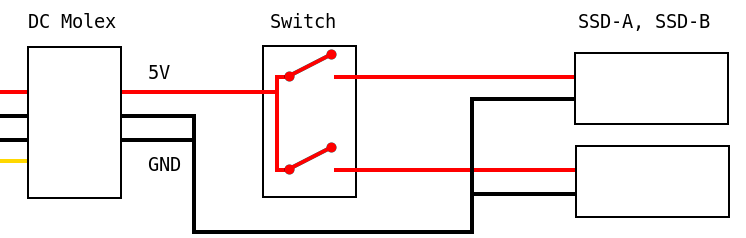
What do I mean by switch the power? Take the power output from the PSU, run this through a switch with 2 outputs, connect each output to separate disks. If the disk does not receive power, it does not respond on the data cable, so it does not get used in the system. Therefore, the data cable can be left connected and not modified. The switch has positions to pass through the power from PSU output, out of the switch as a disk input. Switch it to the other position, and that disk input has no power, power is provided to the other disk input. Below is a build out diagram of this too.
Circuit Design
Let’s break this down. Part 1, coming from the PSU is a Molex connector. Originally I had the SATA power connector, but this looks far more fiddly to cut and re-patch than the molex connector. Looking at the SATA power connectors pin out on Wikipedia we can see that for my needs the additional pins are not needed.
Circuit Design
Molex vs SATA power. The Molex connector does not offer the 3V that the SATA power connector does, but my SSD takes an input of 5V. Molex does offer the 12V, but again I don’t need this for my SSDs, so have simply snipped that off. The SATA power specification also has some pins for pre-power of some of the components, which prepares it to take full power to the SSD. That is to say, these additional pins are for hot-plugging the SSD, an action I don’t plan on doing.
Next we are taking from the Molex, a 5V live wire and two ground wires which I bundle together. The switch takes the 5V as input and dependant upon the switch position passes the 5V out 1 of the 2 paths. Quite straight forward really.
- Switch Position A, 5V live power is delivered to SSD-A.
- Switch Position B, 5V live power is delivered to SSD-B.
Switch On Case
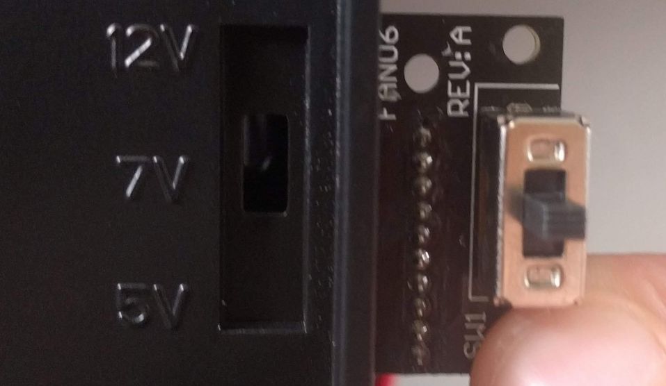
If the switch is difficult to reach, it will be too cumbersome to switch. Or too easy to reach, it may be accidentally switched. What fits right really comes down to your exact case and desk set-up. I was quite fortunate in this, as my case came with a FAN switch that I did not use (preferring to let the motherboard control fans). This switch is built into the case, at the front so easy to access, but behind a door to prevent accidental knocks.
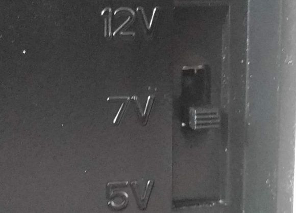
This image shows my case switch removed, next to the slot it will go back into. You can see the switch original positions markings for fans to operate at 5V, 7V, 12V. I simply re-use this to switch the SATA power instead.
Case Switch Placement
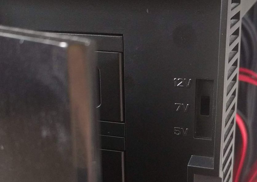
This second image includes the door slightly ajar, showing how the switch is hidden away until I open and flick it up/down. The case is a “Fractal Design R4”, they have much better images and renders of the case as a whole on their website.
Case Switch Placement
Project Testing
Now that I know the rough process I’m going to go through, it’s time to do some testing of project feasibility. Some questions are:
- Does the SSD work with the 5V power?
- Which pins line up at the different switch positions?
- Does the switch pass enough power through?
Does the SSD work with the 5V power?
The label on the SSD says that it does, but to test I simply cut the 12V from a cable and plugged it all together. The SSDs were detected and booted without concerns.
Which pins line up at the different switch positions?
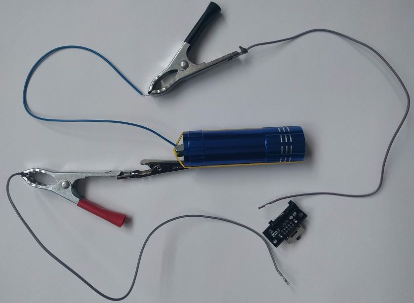
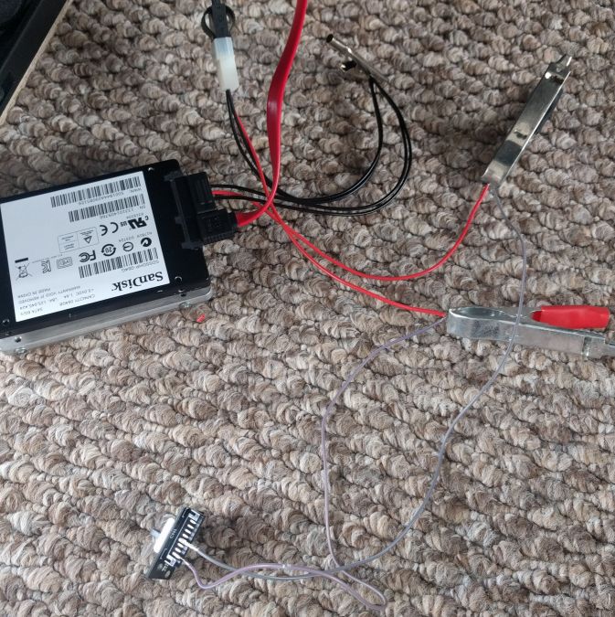
I couldn’t see any markings on the switch that allowed for a pin-out lookup. Additionally, there are 10 pins on the switch, fronted by a connector. For a 3 position switch I only ever expected 6 maximum, 4 minimum, pins for combinations. So I had to do some testing to see what was happening within the switch. I don’t have any electronics testing kit, so I went Ray Mears and used what was around me. Here’s my testing rig.
Switch Test Set-up
I took the end off of a torch, clipped some bits of spare cable, wired it to the switch. The battery pack on the inside had to keep pressure on the spring at the end, so I stuck a nut on it and wrapped it with an elastic band. This also allowed me to wrap the wire around the nut, which was much easier than trying to keep touch with the contact.
At this point it was a matter of putting wire A on pin 1, then wire B on pins 2 through to 10, taking note of what lights up. Repeat again with wire A on pin 2 and so forth. That gave me a table of paths for switch position A, repeated for B, and C. Interestingly the result wasn’t straightforward, there was many outputs per position and inputs, including many overlapping. So despite having 3 positions on the switch, I could only find 2 positions that had non-overlapping pins. My pin-out map is shown below, highlighting that input 2 and 4 can be used for distinct output pins.
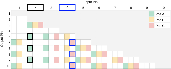
Switch Pin-out Map
I saw no way to have a 3rd distinct option from this pin-out map. Anywhere where ‘Pos B’ (yellow) appeared it overlapped with another. Input 2 and 4 do not overlap at all, nor does 3 and 4 but these pins are closer on the switch so easier to cross touch wires. I would have liked a third option, I could have purchased a switch for this, but this case has pre-made cut outs and screw holes for this exact switch and board. I do not understand why this switch has so much overlap, perhaps it’s not even the switch but the board which it is connected, I don’t see the purpose of it. I did not test direct on the switch, as the board offered a connector with clear distinct pins, to which I could slot over some cable wraps as shown in the images above.
Does the switch pass enough power through?
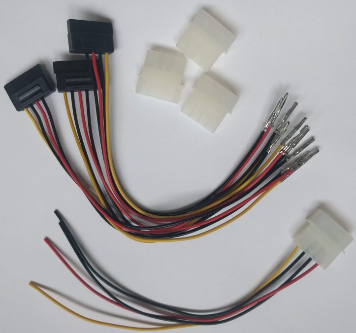
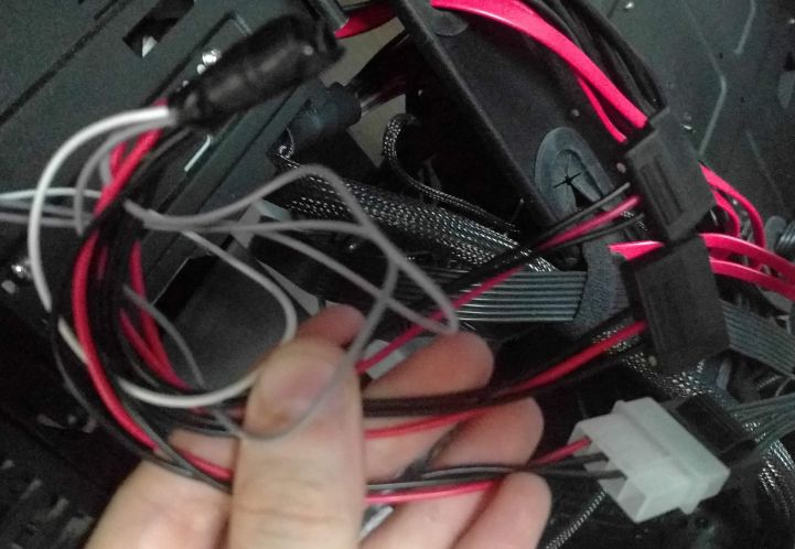
To test everything together I mocked up the elements together. Below you can see the molex from my PSU (black) into a molex that is part of this system (white). From there I combine grounds with a SATA power connector into the SSD. The 12V wire is removed/trimmed from both components. The 5V wire is clipped to some spare cable I have which easily slots over the connector pins. I booted up the PC and checked if the SSD was seen correctly, then repositioned the input and output pins to test the alternative switch position. Both tests completed successfully.
SSD Power Switch Mock-up
I started off with multiple connector cables, removing pins where appropriate, and snipping where pulling isn’t possible. These cables cost less than �5 on eBay, the investment to the project testing was very minimal.
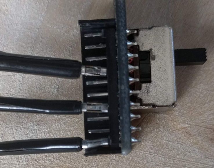
Switch Close-up
Also shown is the pin connector cable, with some electrical tape to prevent some cross connections. Here you can clearly see the connector, 10 distinct pins and how the cable wraps fit over these pins.
Switch Close-up
Completion
To complete I simply used a lot more electrical tape, some twisting, and a little bit of solder. It wasn’t a pretty piece of work in the end, but it is functional, and that ugliness can all be hidden within the case along with the rest of the cable spaghetti.
Switch Complete Inside
Slap on the side of the case, squeezing in all the cables, and all we can see on the front (when the door is open) is the switch face, as designed by the case manufacturer, cleanly and simply.
Switch Complete Outside
Areas for Improvement
This project isn’t perfect, but is simple and straightforward, using what I had available. To improve there are a few internal things such as better soldering, cable colours, etc. Also, I could have tried to source a switch that fits the case, whilst offering a clear 3 distinct options for the pin-outs. But for my use case, none of this is necessary, so I don’t expect to be making these changes unless I hit an issue.
Final Thoughts
Even since doing this, I have broken grub2 a few times whilst playing with Arch (unsuccessfully). But since it was only Linux on disk, the fix takes 5 minutes, “bish bash bosh”.
To switch between Linux and Windows is very simple, just shutdown, flip the switch, boot and go grab a tea. If I’m a bit impatient, I hit the reset button, flip the switch, then reset again. But there is no need to monitor for the boot menu or anything like that.
I can’t imagine having a system without this now, which may be challenging if I ever decide to update my case, this isn’t a typical requirement. I suspect something like that would use another fan switch, or mounted onto an unused drive face plate.